Switch stack ring and uplinks
I really enjoy discussing network design and deploy details with colleagues, customers and fellow network engineer.
I find these discussions challenging, stimulating. An open, sincere and collaborative discussion gives a chance to better understand the real needs, fears, doubts of other professionals and to validate knowledge, expose gaps and most of all I learn a lot.
This is still valid when discussing Data Center design or simpler topics like how to cable switch stacks. It may seem trivial but if the stacks are many, delivery people are just a bit more than electricians and cable pullers and the time available is very tight even small details can have an impact in the overall project outcome.
Switch stacks
The main topic of the discussion was where to connect the uplinks from access switch stacks to distribution switches for better performances, resiliency and simplicity.
Ring topology
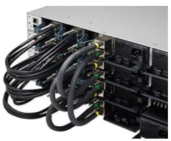
Let’s start from the basics. How are stack cables connected? In most cases cables are crossed between units and one cable connects the last unit to the first, closing the ring.
This method, called daisy chained ring, is easy but requires one longer cable per stack that may be hard to install in case patch panels and patch management rings are installed between each unit.
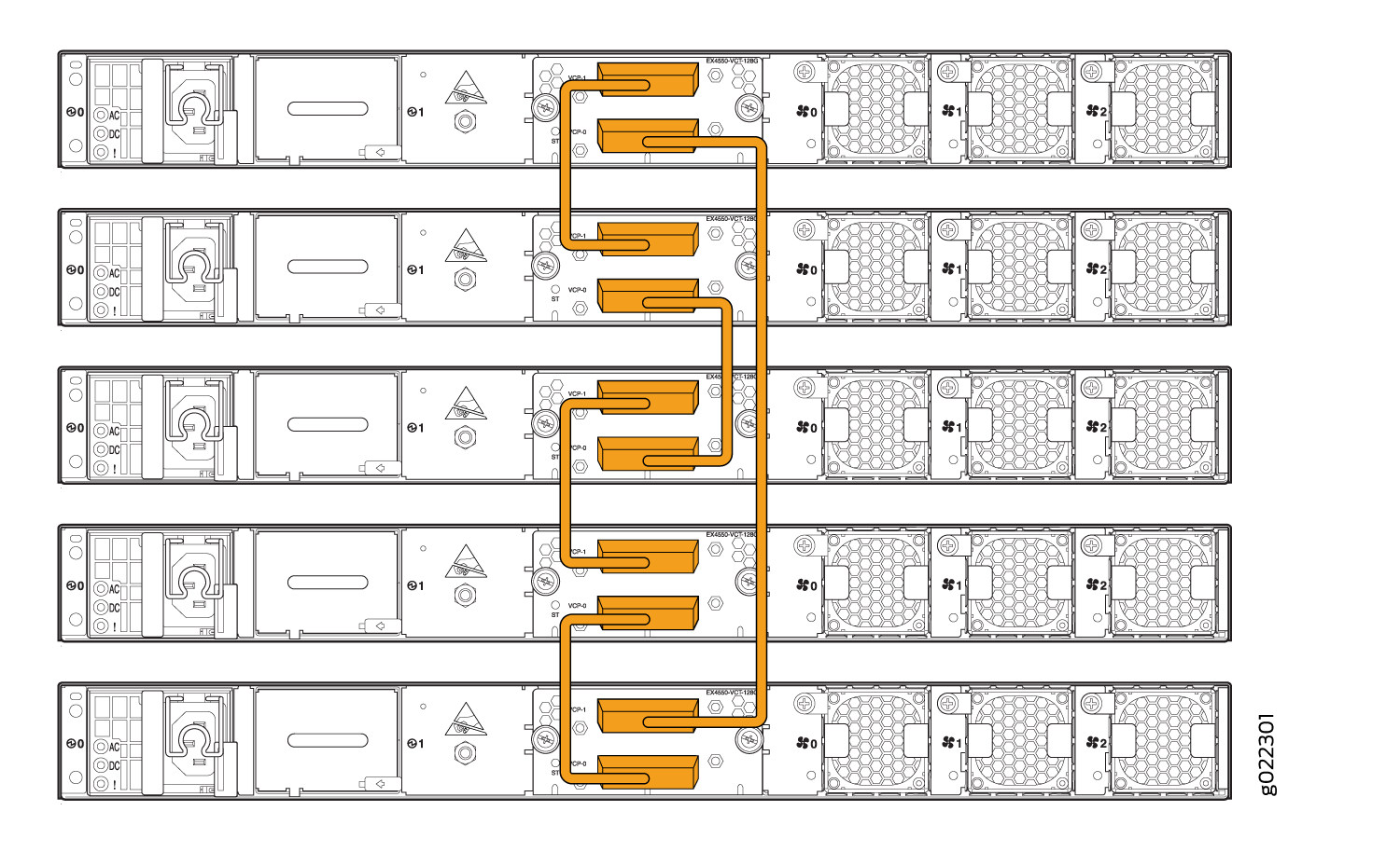
I often get some suprised looks presenting an alternative cabling method, commonly called braided ring:
This type of ring is a bit more complicated to realize but has some advantages:
- no need to provide a longer cable - BOMs are simpler
- no need to find the correct cable length; how long? It depends on the number of stack members and there are some limitations on the cable length
- switches can be further apart. This allows horizontal stacks (switches installed in adjacent racks) or more space between units to fit cabling management rings.
In a network were stacks can be up to 9 units this variability and distances must be considered.
I’m not saying one topology is better than the other, the correct answer is it depends but at least there are two choices.
Stack uplinks
To understand why some choices are better than others regarding where to connect the stack uplinks we need to go deeper on the stack technology:
The switches in a stack are connected with special stack interconnection cables. These are the StackWise Plus cables. These cables create a bidirectional closed loop path. Within this loop, packets are allocated between two logical counterrotating paths so that if a switch or cable failure is detected, traffic is wrapped back around across the remaining path. This allows the stack to continue to function, without partitioning, if a switch were to go offline.
Source: Cisco Catalyst 3850 Series Switches StackWise-480 Architecture White Paper
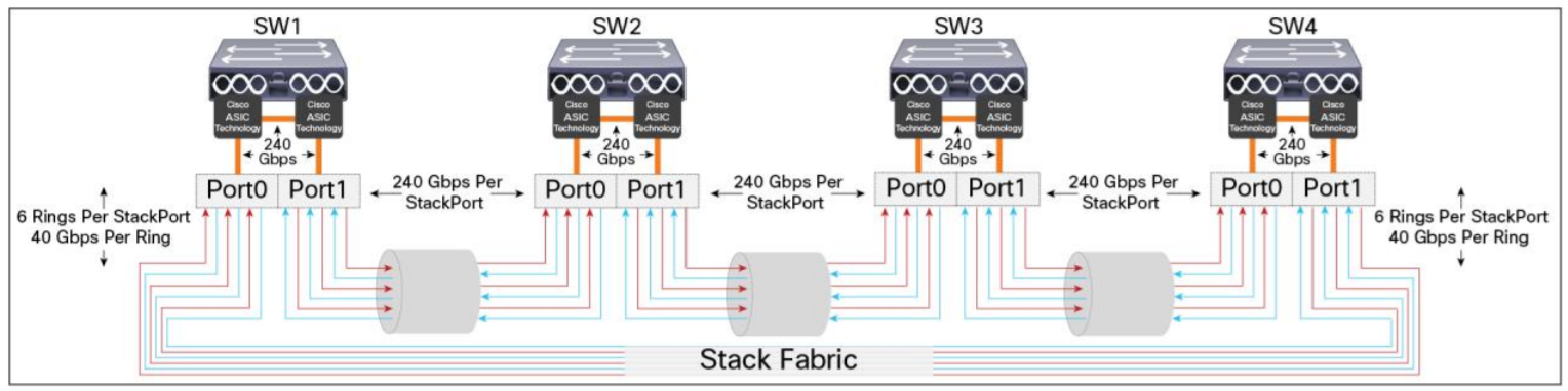
A stack of Cisco 3850 provides a 240Gpbs ring between stack members.
I can’t find the technical document but I recall discussing the stack ring some time ago at a Cisco event, I remember someone saying traffic is sent to the port with less hops to the destination.
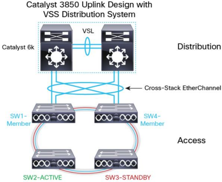
For example in the topology below there is a stack of 4 units. Connecting uplinks on units 1 and 4 means units 2 and 3 are one hop away from the uplink but in case of fault of unit 1 or 2 the uplink placement would be sub-optimal from the point of view of ring use.
In a bigger stack with up to 9 members the placement of the uplink ports may have an impact on the ring usage. The optimal option depends by the number of stack members and uplinks.
Example with 2 uplinks and up to 9 stack members:
| STACK MEMBERS | OPTIMAL UPLINK PLACEMENT |
|---|---|
| 2 | units 1 and 2 |
| 3 | units 1 and 2 |
| 4 | units 1 and 3 |
| 5 | units 1 and 3 |
| 6 | units 1 and 4 |
| 7 | units 1 and 4 |
| 8 | units 1 and 5 |
| 9 | units 1 and 5 |
Hosts
Don’t forget that the ring is used also for est-west traffic between hosts connected to the stack. In case of bottleneck it would help to move hosts between units to find the best compromise.
How to spot a bottleneck? Start looking for drop counters on ports.
The pragmatic designer
Every discussion at some point should pause to consider the most important question: what problem are we trying to solve?
In this particular case, after analyzing many factors including maintainability, standardization and performances, the final decision was to connect the uplink always on units 1 and 2 of the stack, no matter how many units.
The reasons seem obvious but were included in documentation:
- simpler to deploy
- easier to spot mistakes
- simpler automation scripts to create configurations based on templates and verify connections
- impact on uplink performances is reasonable - ring use is not expected to reach maximum values
Lesson learned
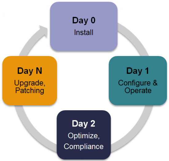
The role of a architect includes considerations about day 0 (install) and day 1 (configure and operate) of the project life cycle.
The final decisions may not be optimal for every single aspect. Performances may have lower priority than simplicity for example.
At the end of the day I enjoyed the discussion, the customer was happy with the shared decision process and professional support and the team in charge of network installation and configuration will work on a detailed design documents that leaves no gray areas.