Cisco ASA VPN with over overlapping addresses and twice NAT
IP addressing design is a topic that follows every networker from the basic to the architect level of experience.
Usually we just pick a random range from RFC1918 and address all the devices.
But then VPN happens, and with VPN comes the risk of overlapping.
How do we fix overlapping? With NAT of course!
In this post I'll show how to use twice NAT to allow VPN connections with overlapping addresses.
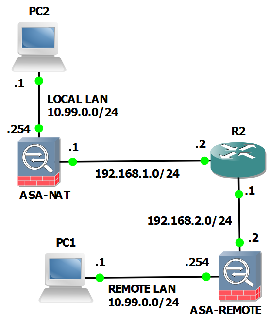
Topology:
Constrains:
- to change addressing of any network is not an option
- no NAT on ASA-REMOTE for the VPN
Our tools:
- Cisco ASA 5510 releas 8.4(2)
- twice nat
We can see in the topology both local and remote network use addressing 10.99.0.0/24. The local PC2 must reach remote PC1.
The plan
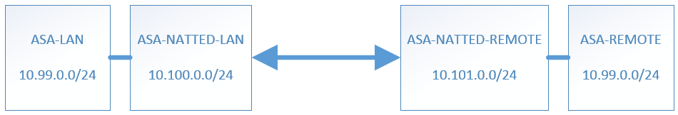
To fix the overlapping we need to NAT on ASA-NAT both networks to two subnets not used on both sides.
Network LOCAL LAN 10.99.0.0/24 will be seen as 10.101.0.0/24 from REMOTE LAN.
Network REMOTE LAN 10.99.0.0/24 will be seen as 10.100.0.0/24 from LOCAL LAN.
A full network NAT will be used so a host 10.99.0.1 on LOCAL LAN will be natted ad 10.101.0.1 to REMOTE LAN. This is a better choice than nat overload when remote services must be reached.
VPN Configuration
If you're familiar with VPN configuration on ASA or IOS you know a cryptomap is involved. A cryptomap is an ACL that defines the traffic that will be encrypted and sent to the remote VPN peer.
In out case the cryptomap on device ASA-NAT will be:
access-list outside_cryptomap extended permit ip 10.100.0.0 255.255.255.0 10.99.0.0 255.255.255.0
This could be quite confusing, the destination address is the same subnet of the LOCAL LAN, but we'll see why it works (hint: order of operation.
VPN configuration on device ASA-NAT:
crypto ipsec ikev2 ipsec-proposal AES256
 protocol esp encryption aes-256
 protocol esp integrity sha-1 md5
crypto map outside_map 1 match address outside_cryptomap
crypto map outside_map 1 set peer 192.168.2.2
crypto map outside_map 1 set ikev2 ipsec-proposal AES256
crypto map outside_map interface outside
crypto ikev2 policy 1
 encryption aes-256
 integrity sha
 group 5 2
 prf sha
 lifetime seconds 86400
crypto ikev2 enable outside
group-policy GroupPolicy_192.168.2.2 internal
group-policy GroupPolicy_192.168.2.2 attributes
 vpn-tunnel-protocol ikev2
tunnel-group 192.168.2.2 type ipsec-l2l
tunnel-group 192.168.2.2 general-attributes
 default-group-policy GroupPolicy_192.168.2.2
tunnel-group 192.168.2.2 ipsec-attributes
 ikev2 remote-authentication pre-shared-key cisco123
 ikev2 local-authentication pre-shared-key cisco123
VPN configuration on device ASA-REMOTE:
crypto ipsec ikev2 ipsec-proposal AES256
 protocol esp encryption aes-256
 protocol esp integrity sha-1 md5
crypto map outside_map 1 match address outside_cryptomap
crypto map outside_map 1 set peer 192.168.1.1
crypto map outside_map 1 set ikev2 ipsec-proposal AES256
crypto map outside_map interface outside
crypto ikev2 policy 1
 encryption aes-256
 integrity sha
 group 5 2
 prf sha
 lifetime seconds 86400
crypto ikev2 enable outside
group-policy GroupPolicy_192.168.1.1 internal
group-policy GroupPolicy_192.168.1.1 attributes
 vpn-tunnel-protocol ikev2
tunnel-group 192.168.1.1 type ipsec-l2l
tunnel-group 192.168.1.1 general-attributes
 default-group-policy GroupPolicy_192.168.1.1
tunnel-group 192.168.1.1 ipsec-attributes
 ikev2 remote-authentication pre-shared-key cisco123
 ikev2 local-authentication pre-shared-key cisco123
NAT Configuration
All the magic happens on device ASA-NAT.
First step - create the network objects:
ASA-LAN is the local network:
object network ASA-LAN
  subnet 10.99.0.0 255.255.255.0
ASA-REMOTE-LAN is the remote network:
object network ASA-REMOTE-LAN
  subnet 10.99.0.0 255.255.255.0
It is the same as AS-LAN but I used different names to make the nat command more clear.
ASA-NATTED-LAN is how the local network is seen from the remote network:
object network ASA-NATTED-LAN
  subnet 10.100.0.0 255.255.255.0
ASA-NATTED-REMOTE is how the remote network is seen from the local network:
object network ASA-NATTED-REMOTE
  subnet 10.101.0.0 255.255.255.0
Second step - the NAT command:
nat (inside,outside) source static ASA-LAN ASA-NATTED-LAN destination static ASA-NATTED-REMOTE ASA-REMOTE-LAN net-to-net
The first part of the command source translates the local network ASA-LAN (10.99.0.0/24) as ASA-NATTED-LAN (10.100.0.0/24) when talking to ASA-NATTED-REMOTE (10.101.0.0/24)
The second part of the command destination translates the remote network ASA-NATTED-REMOTE (10.101.0.0/24) as ASA-REMOTE (10.99.0.0/24).
The final result creates a packet with source 10.100.0.0/24 and destination 10.99.0.0/24 that perfectly matches the cryptomap we created so the traffic correctly enters the VPN.
Order of operations
For a better understanding of the whole process we can use the packet tracer and see the steps.
The command is:
ASA-NAT# packet-tracer input inside tcp 10.99.0.1 http 10.101.0.1 http
I removed some lines for a better output.
Phase: 1
Type: ACCESS-LIST
Result: ALLOW
In phase 2 the destination IP of the packet is un-natted from 10.101.0.1 to 10.99.0.1.
Notice: there's no routing involved here, the traffic is diverted to the outside interface by the NAT rule, overriding the routing table.
Phase: 2
Type: UN-NAT
Subtype: static
Result: ALLOW
Config:
nat (inside,outside) source static ASA-LAN ASA-NATTED-LAN destination static ASA-NATTED-REMOTE ASA-LAN
Additional Information:
NAT divert to egress interface outside
Untranslate 10.101.0.1/80 to 10.99.0.1/80

Phase: 3
Type: IP-OPTIONS
Result: ALLOW
In phase 4 the source of the packet is translated from 10.99.0.1 to 10.100.0.1:
Phase: 4
Type: NAT
Subtype:
Result: ALLOW
Config:
nat (inside,outside) source static ASA-LAN ASA-NATTED-LAN destination static ASA-NATTED-REMOTE ASA-LAN
Additional Information:
Static translate 10.99.0.1/80 to 10.100.0.1/80
The traffic matches the cryptomap:
Phase: 5
Type: VPN
Subtype: encrypt
Result: ALLOW
Config:
Additional Information:

Phase: 6
Type: NAT
Subtype: rpf-check
Result: ALLOW
Config:
nat (inside,outside) source static ASA-LAN ASA-NATTED-LAN destination static ASA-NATTED-REMOTE ASA-LAN
Additional Information:

Phase: 7
Type: VPN
Subtype: ipsec-tunnel-flow
Result: ALLOW
Config:
Additional Information:

Phase: 8
Result: ALLOW

Phase: 9
Type: FLOW-CREATION
Result: ALLOW
The final result:
Result:
input-interface: inside
input-status: up
input-line-status: up
output-interface: outside
output-status: up
output-line-status: up
Action: allow
Final considerations
I want to thank my friend (and happy customer) Andrea (the creator of Unified Networking Lab for the question he sent me that gave me the chance to lab this feature and write this post.
I use to configure NAT on both firewalls for this kind of overlapping but in this case we wanted to have the same results without any NAT on remote firewall.
Comment if you need clarifications or help on this topic.